CAD the motor base and arm!
- Session
- 4 of 33
- Date
- 26 April 2026
- Time worked
- 2 h 7 min
- Reading time
- 2 min
- Images
- 8
Firstly, I started with the 2D design and “copying” the motor sizes, holes, etc. At first I struggled finding the diameter tool and also understanding the motor sketch, especially with the 4× M2 holes. That confused me because I thought the 1.5 mm was the diameter of the holes, but it was actually the radius.
Then I made another mistake: I thought the 1.5 mm radius was for the holes, but it was actually for the outline. For the hole size I had to search it up on the internet, which was M2 (about 1.5 mm diameter). I also had to pay attention to a recess in the middle of the motor (the side where it will be mounted), so I had to cut out a small hole with a diameter of about 4 mm.
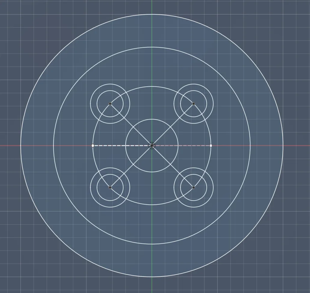
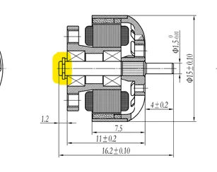
After that I continued with the 3D design. I extruded the platform to 5 mm for stability, but not more, to save weight.
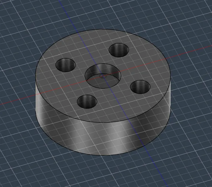
I also thought about making the plate a bit bigger than the motor itself, so I added about 5 mm around it for more stability and so the arms can connect better to the motor platform.
Then I remembered that I should include about 0.2 mm tolerance, so I updated the design for that.
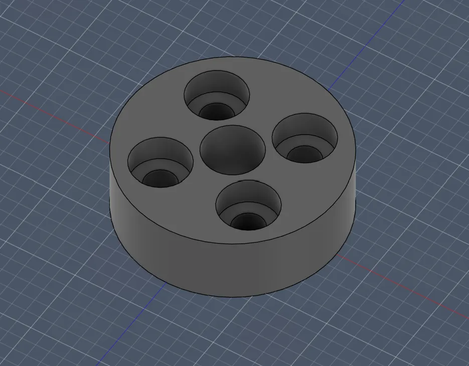
After that I checked the screw length. The holes have a depth of about 1.5 mm and the plate is 5 mm thick (total ~6.5 mm). The screw head also takes about 1.5 mm (hidden in the platform), so I calculated:
7.5 mm − 1.5 mm = 6 mm
So I will use M2 6 mm screws, which luckily exist.
At the end I extruded all the holes, so it looked like this:
After that I started with the “2 arms per motor” design.
First, I checked where the cable from the motor comes out, because the cable should go through the 45° angled arm that goes directly to the center.
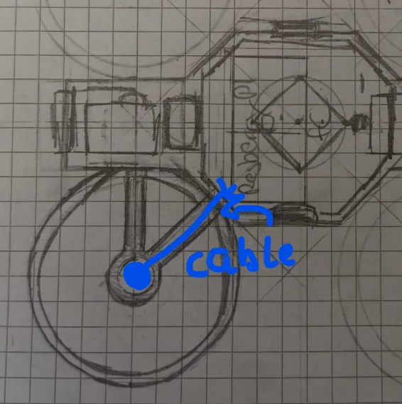
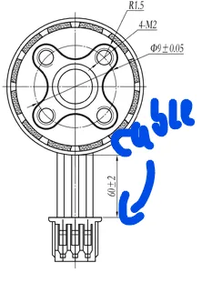
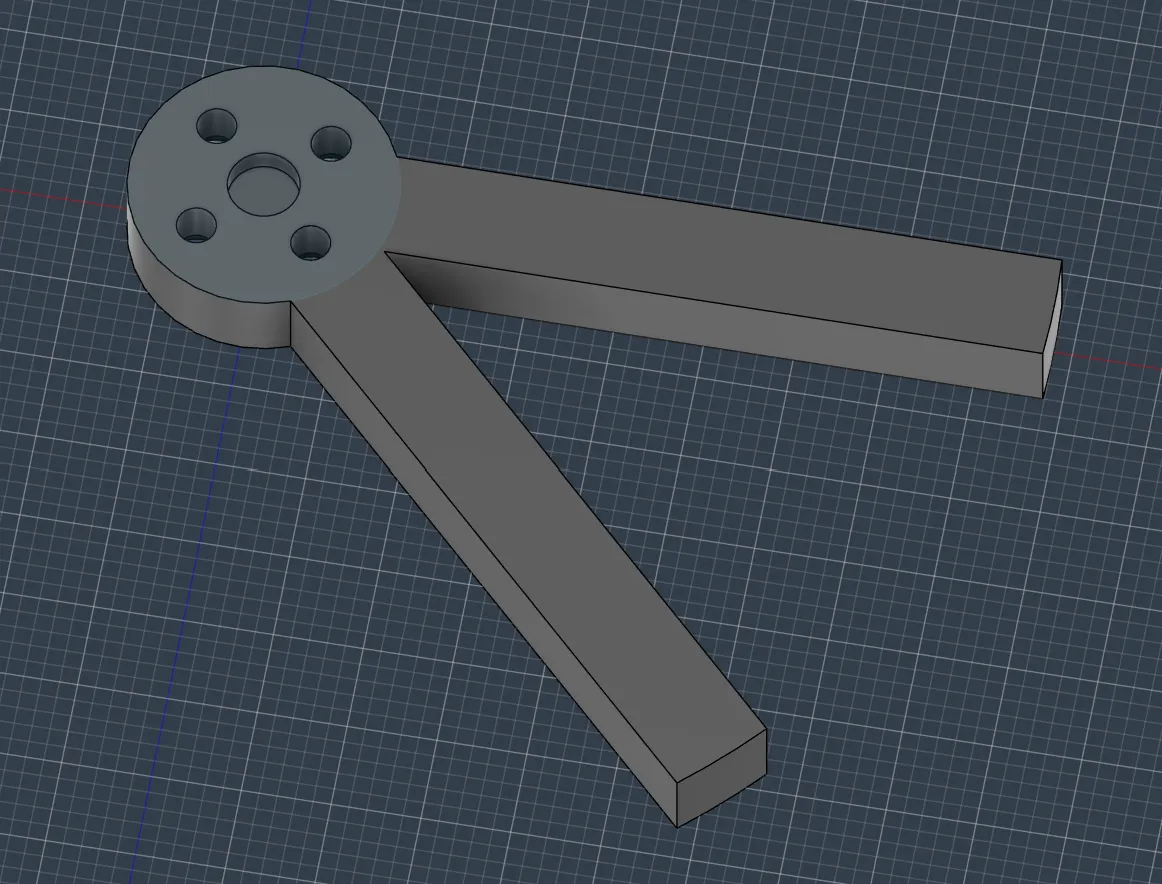
I made the arm go exactly 44 mm from the center of the motor, based on my previous planning. For the width I used 6 mm, and for the height I used the same as the base: 5 mm.
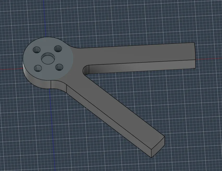
Then I also rounded the edges between the arm and the motor base:
Happy with today’s progress. I learned a lot in CAD design and I like the arm design for the motor. Tomorrow I will continue with the cable channel in the arm and then the main base of the drone!!! Pretty excited!
Session recordings
Timelapse recordings of this session.