FINISHED THE PCB!!!!
- Session
- 25 of 33
- Date
- 21 May 2026
- Time worked
- 2 h 18 min
- Reading time
- 3 min
- Images
- 19
I firstly drew the big 5V connection on the Powerplane
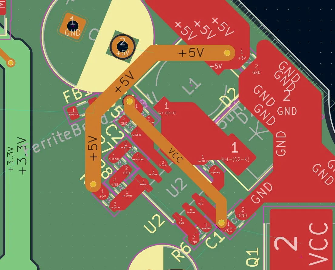
and updated the vias at the VCC connection so that they are bigger, and then I continued on making the GND connection.
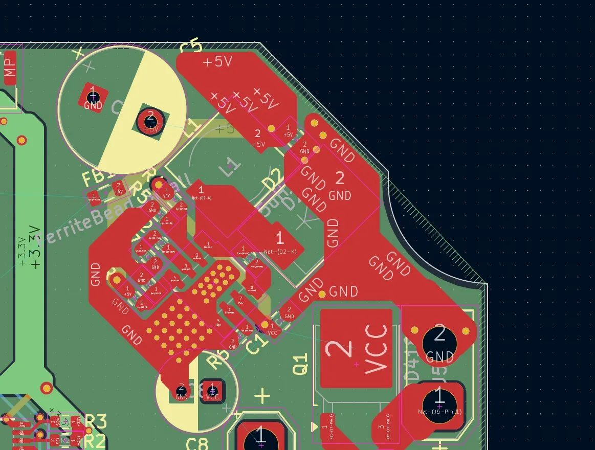
I started by connecting the top part's 3 connections together and then connected that with the down GND connection. And then I saw that in the datasheet they showed that they made a huge GND plate with many vias, and also under the MP part for cooling, optimal flow, and temperature. So after making a hugeee plate and adding the vias (which by the way were very hard because all had to have the same distance but they were awkwardly rotated, but after a bit of trying I got that)
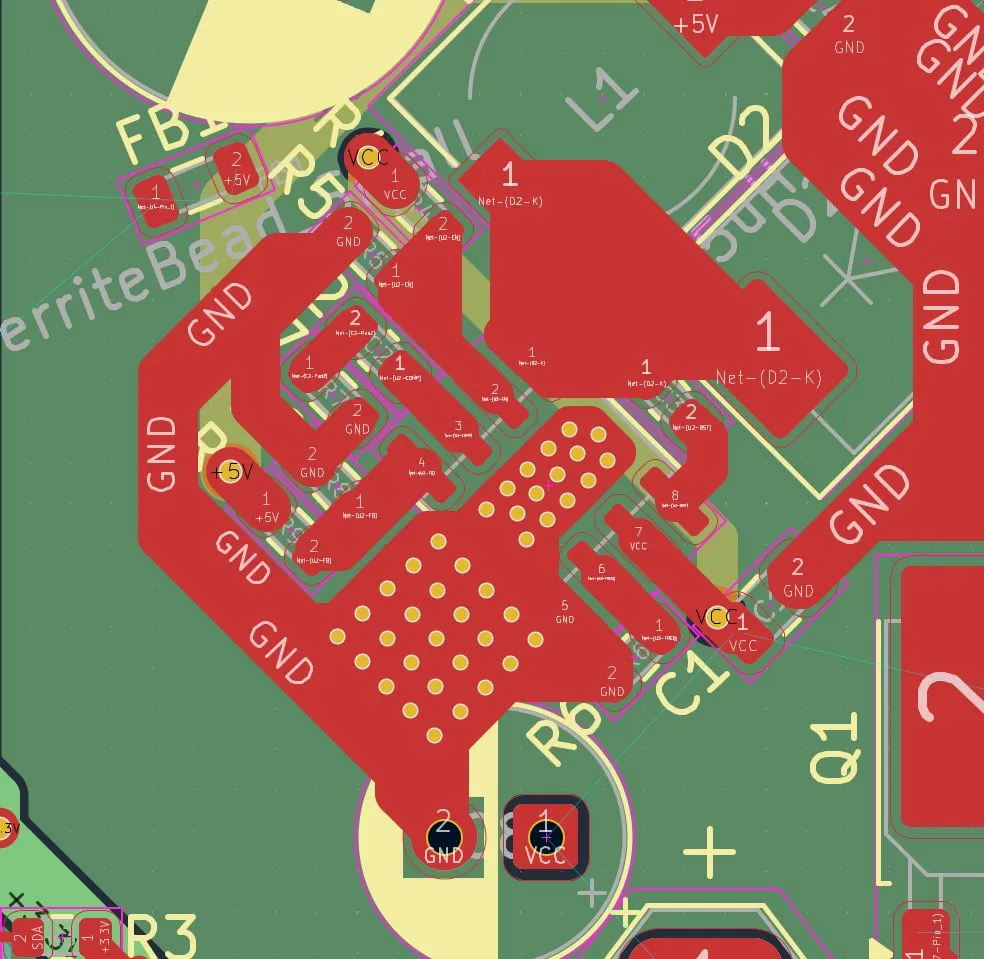
but then I saw that I had some 90-degree angles which wasn't that good. So I quickly removed them by adding a diagonal trace..
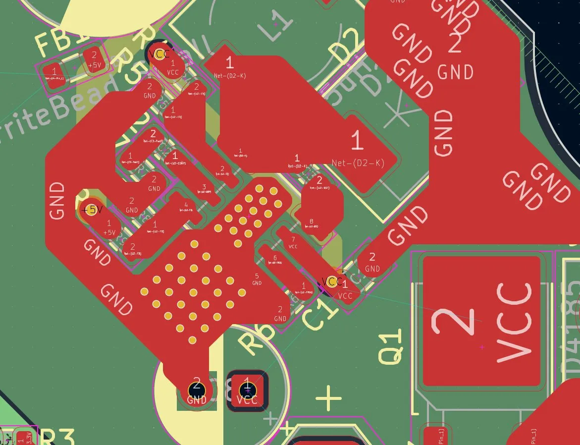
But I saw that I forgot to connect the other GND net with the vias to the GND plate, and also add the GND from the battery connection, but then I saw that there should actually be more vias (4, so I added them).
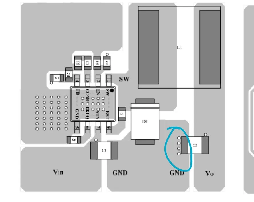
and after implementing it looked like that
Then I continued on connecting the 1st capacitor that is for the servo with the 5V and then also to the FB8.
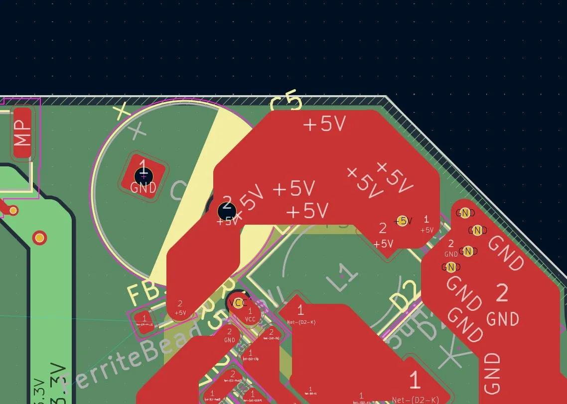
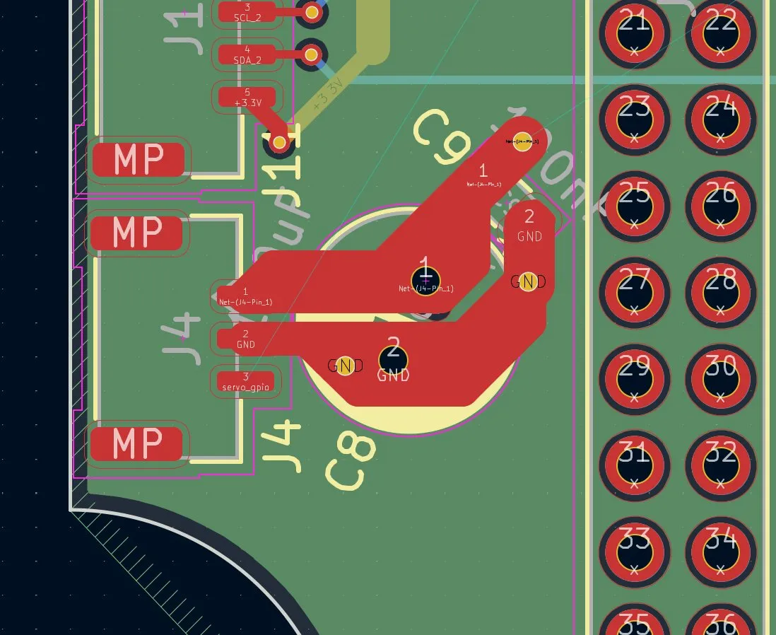
After that, I improved the position of the other 2 capacitors that the servo would need, and made them so that they had the shortest way to the 5V buck converter. And after also connecting those components it looked like that:
I also decided to make the vias for the power bigger: diameter 1.6mm and hole 1mm.
Next, I started with the connection from the 5V power supply to the servo, but I had to pay attention so that the Raspberry Pi power supply wouldn't go all the way up and go to both the FC data connection and sensor, and get false data through noise.
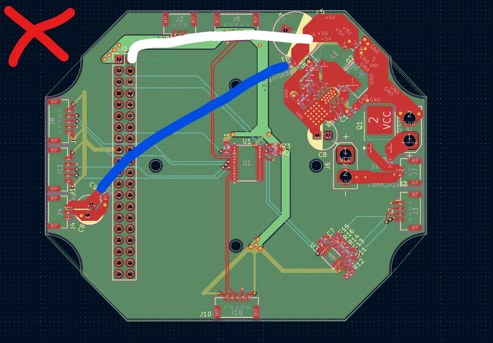
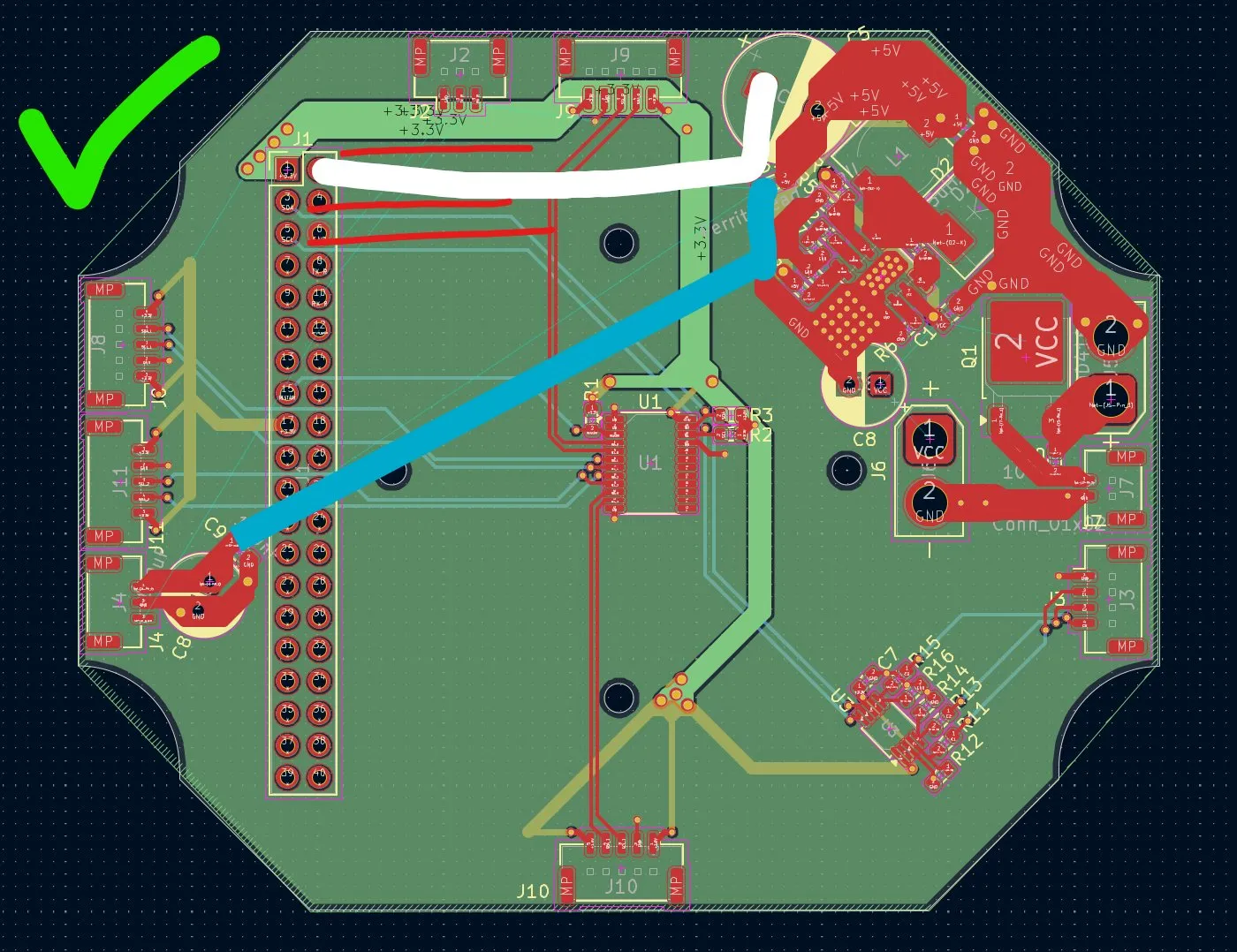
But there was still a problem: the two blue lines (data) were perfectly parallel to the 5V line, which is terrible. So I decided to put them further down.
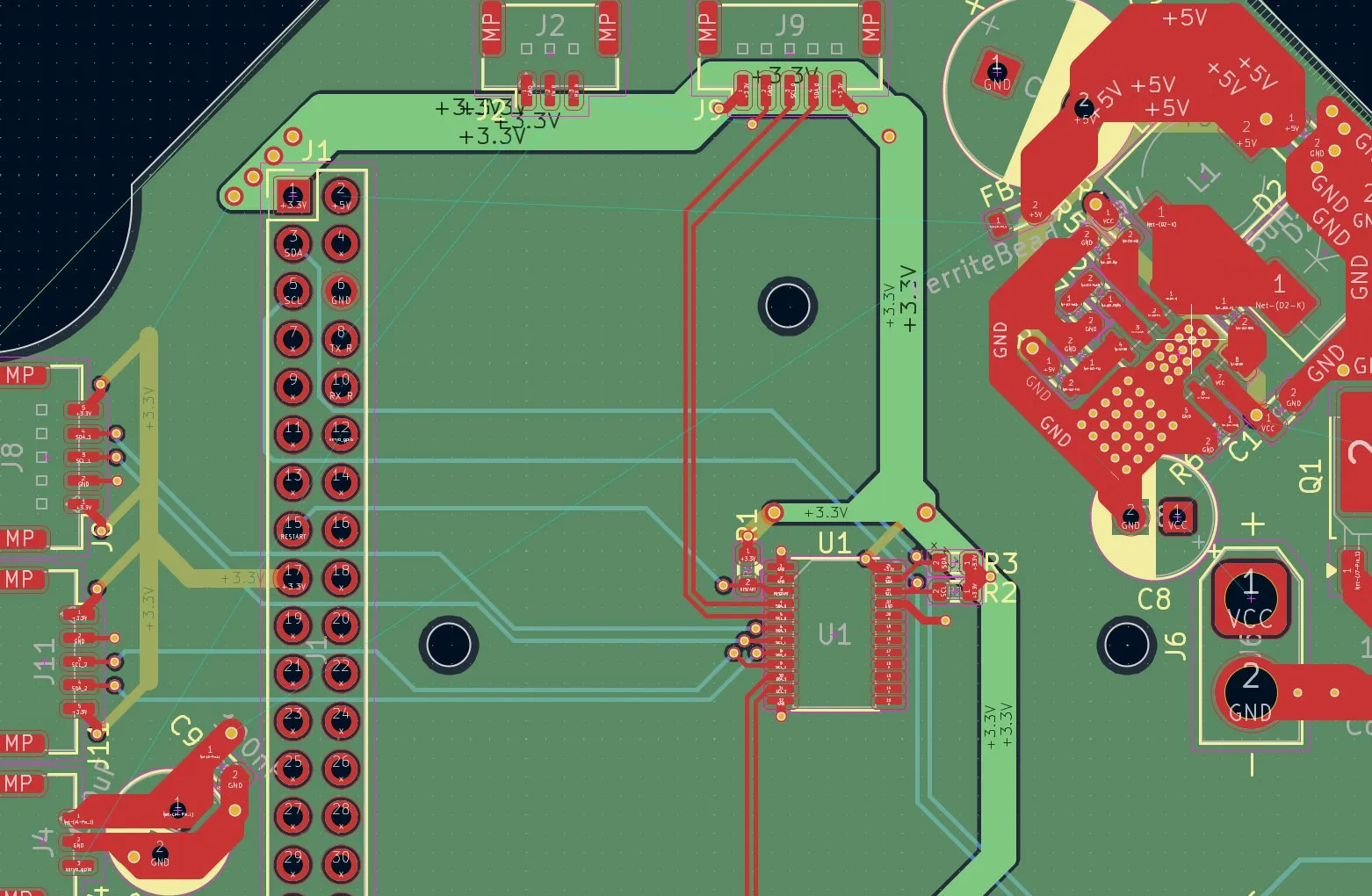
And now I could start, but I forgot that the pins from the Raspberry Pi were blocking a part, so I actually had to go around it.
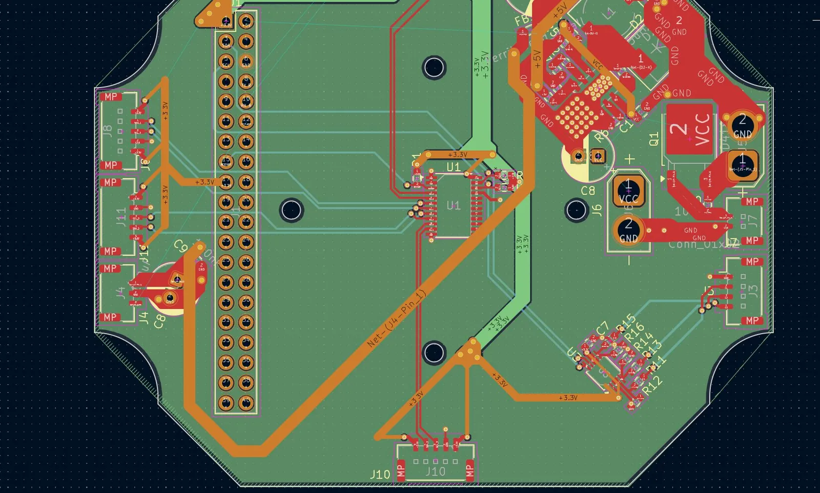
But I noticed I could save some space if I wouldn't turn all to the other side of the 2 capacitors.
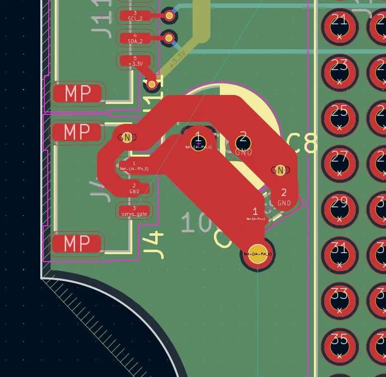
And after turning the components and connecting them again, it looked like that above.
After I recovered it, it looked like this:
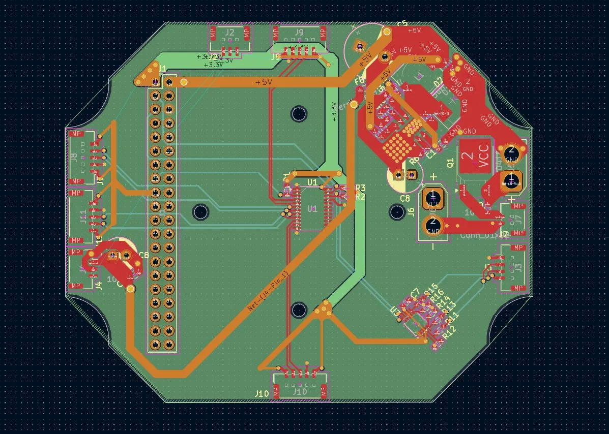
After that, I connected the servo GPIO pin with the servo.
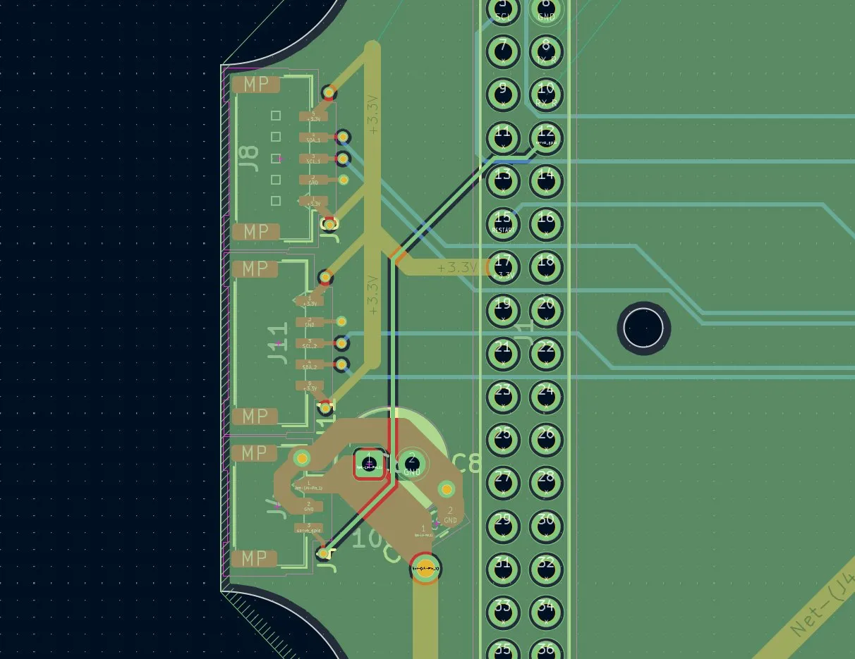
But I thought that if there would be another pin that works with the servo and is further down, that this would be much better. So I searched for a new one, but there weren't really other pins that were PWM-capable, so I didn't change that.
And then I only had to connect smaller things like the TX RX.
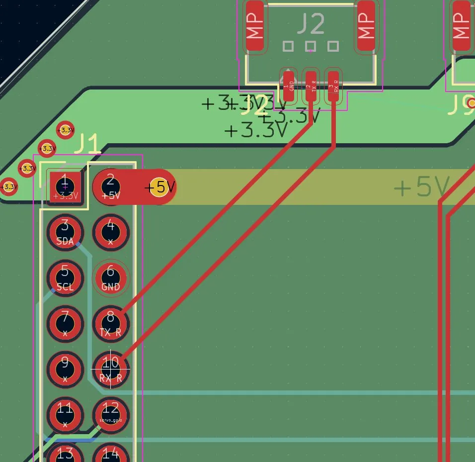
And then, very important, the power to the buck converter and the FC.
And then it looked like that. I tried to make the tracks as wide as possible so that it doesn't heat up.
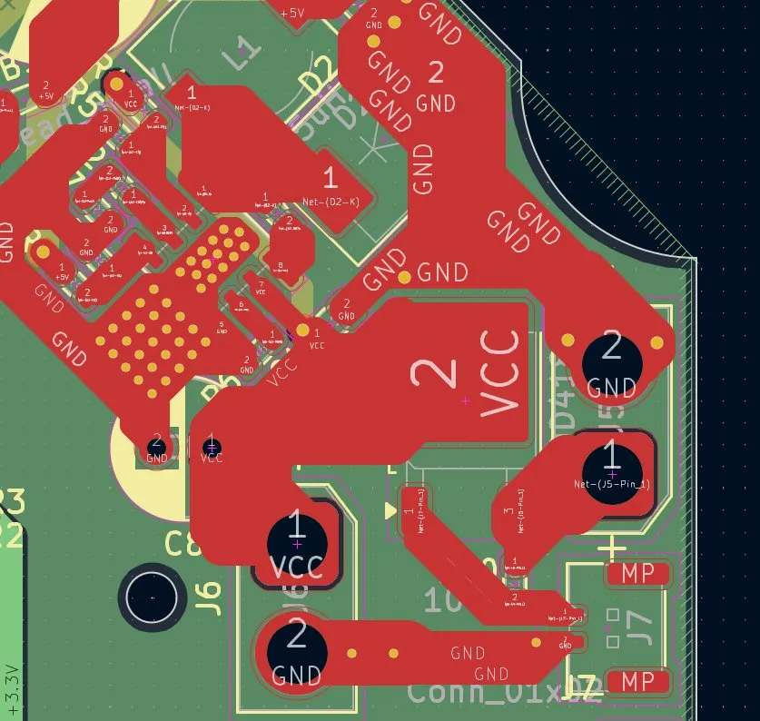
Lastly, I connected the last missing GND connections and checked everything again.
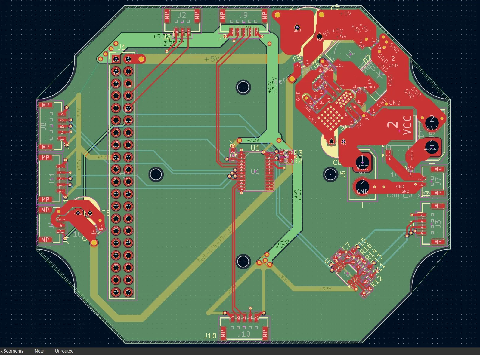
And then I wanted to add GND planes to every layer and to every spot that is free for better absorption and better cooling.
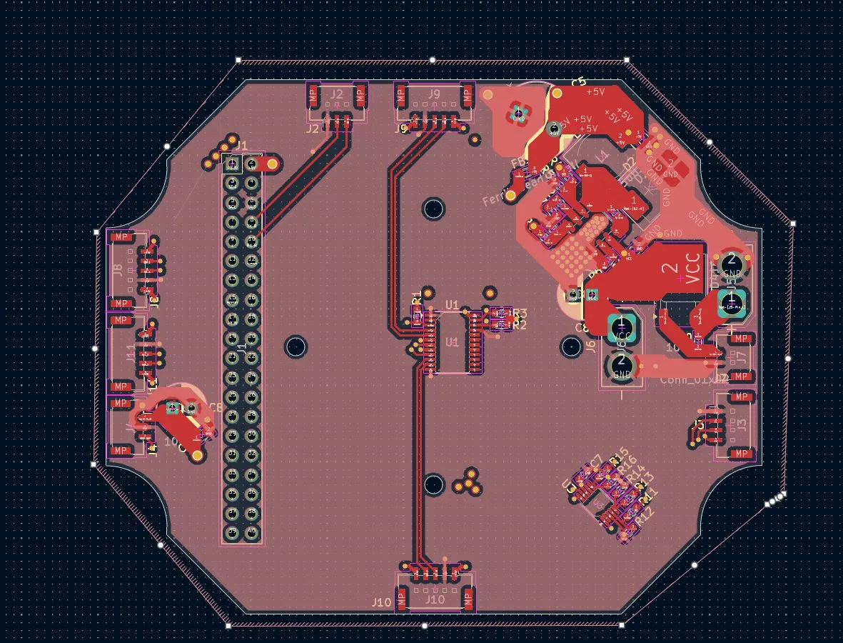
I found out that you can do it the exact same way as for the GND layer, and it worked perfectly! I applied it to the other 3 layers.
Now I only positioned the codes/numbers of the components nicely so I can read them clearly.
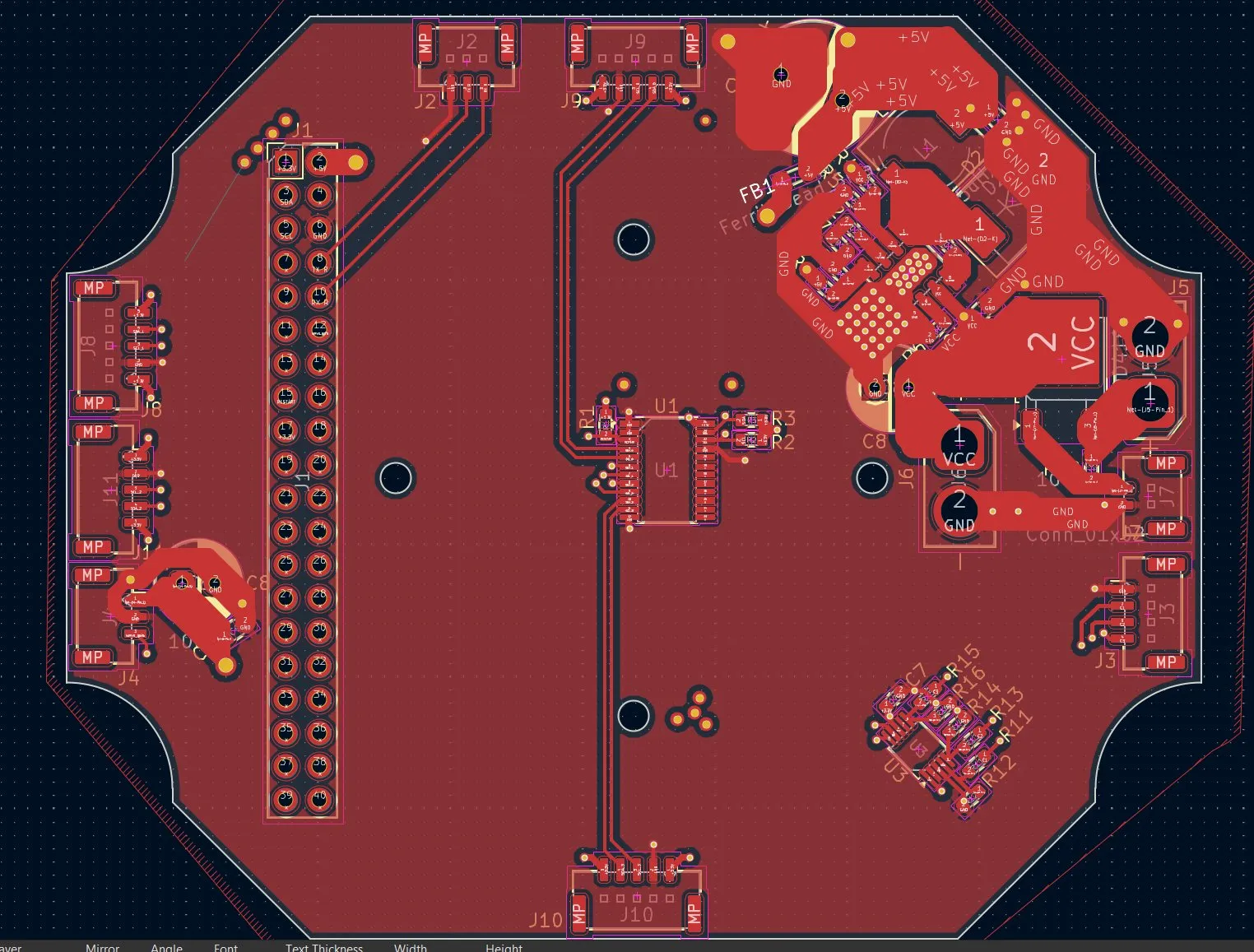
And then I added small detailed pictures like the fan from Hack Club and Fallout, but that didn't work that well and I'm doing that tomorrow.
Overall happy, GOT BASICALLY THE PCB DONE!!!!
Session recordings
Timelapse recordings of this session.