Designing the base of the drone!!
- Session
- 6 of 33
- Date
- 30 April 2026
- Time worked
- 2 h 17 min
- Reading time
- 4 min
- Images
- 10
Firstly, I created the base file where the main base of the drone should be. But before I started designing, I wasn’t sure if the center of gravity would actually be in the middle. So I wanted to calculate everything first to avoid any problems later.
The problem was that I didn’t really know how to do that, but after a bit of googling I found this: https://www.wikihow.com/Calculate-Center-of-Gravity
For calculating the center of gravity you need the position of each part relative to the center and its weight. So I found all values by measuring distances and looking up the weights online:
- Raspberry Pi: +1 cm, 10 g → +10
- Camera: +10 cm, 15 g (took a while to figure out)
- Servo: 7.7 cm, 9 g
- Battery: 76 g, -5 cm
- FC is directly in the middle → no effect
- all other parts are symmetric (motors etc.)
Calc: 10 + 150 + 69.3 − 380 = −150.7
Total weight: 10 + 9 + 76 + 15 = 110 g
Center of gravity: −150.7 / 110 = −1.37 ≈ −1.4 cm
This is not good because the center of gravity should be at 0 cm. So I had a few ideas:
- add weight at the front (about 9 cm in the front)
- increase infill in the front area to add “hidden weight”
After that I started designing:
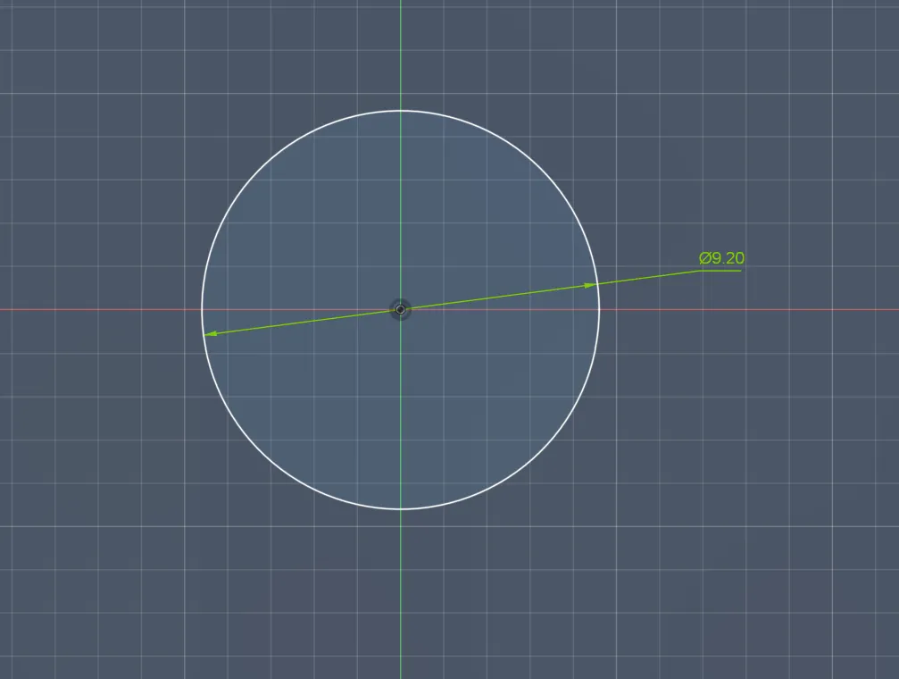
I first made a circle based on my previous drawing. The distance was 2.3 mm, and I scaled it up 4x (to become a diameter and for the sscale 1:2), so I got 9.2 mm diameter.
Then I draw the edges where the arms connect to the base at 45° and 4.6 cm length.
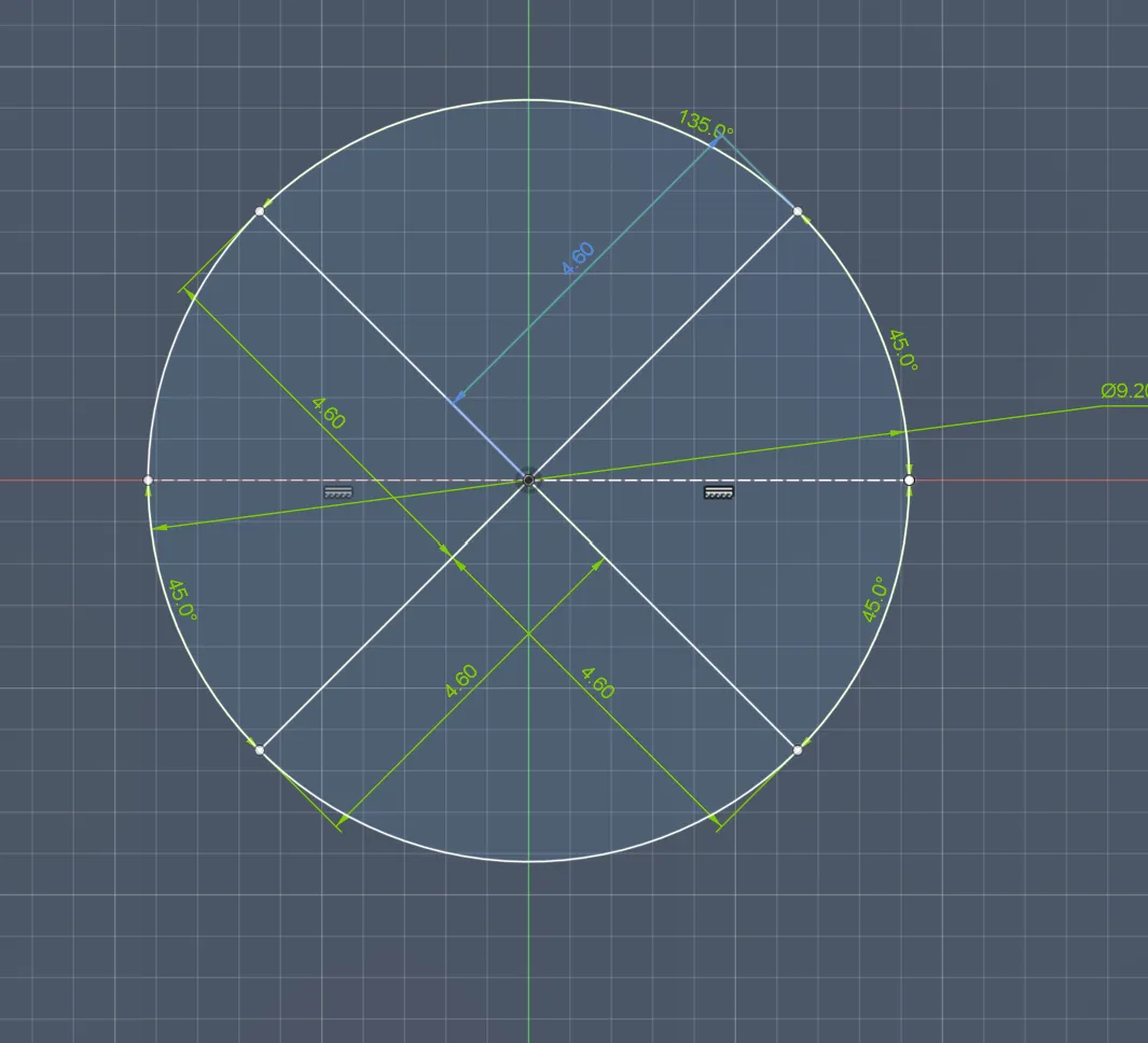
But then I wasn’t sure how big the connection area for the arms should be. So I measured the arm width (6 mm) and multiplied it by 3, which returned 18 mm. From the center that meant about 6 cm spacing on both sides.
While doing that I realized I had made a mistake with some values:
- I accidentally wrote 4.8 mm instead of the correct value 48mm...
So I had to fix and update all doistances… T-T
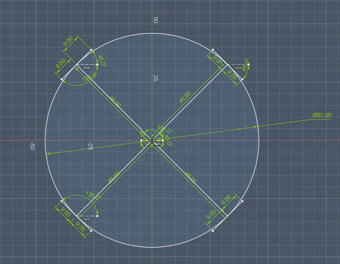
After fixing everything, I added the final connection lines for the arms:
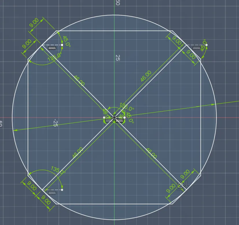
And finally connected everything:
Afterwards, I started designing the rectangle where the camera and servo will sit, and where the second arm connects with the base. For that I first checked my drawing to get the correct scale. In my sketch it was 30 mm, so in real size (1:2 scale) it became 60 mm, and the width was 17 mm → 34 mm in real.
So I created a rectangle with those values:
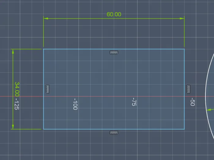
But then I got confused because the rectangle didn’t match my original sketch. I kept checking the measurements, but it still didn’t fit . At that point, I realized that my sketch wasn’t very accurate.
So I decided to first draw the motor positions and propeller radius to understand where everything actually is positioned and where everything should be:
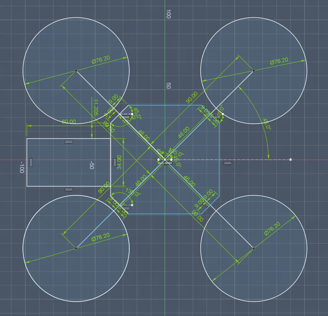
Then I saw that the diagonal arm connections actually matched the larger circles in my sketch, and the smaller ones were the propellers. But the vertical arms didn’t fit properly, so I had to fix the layout.
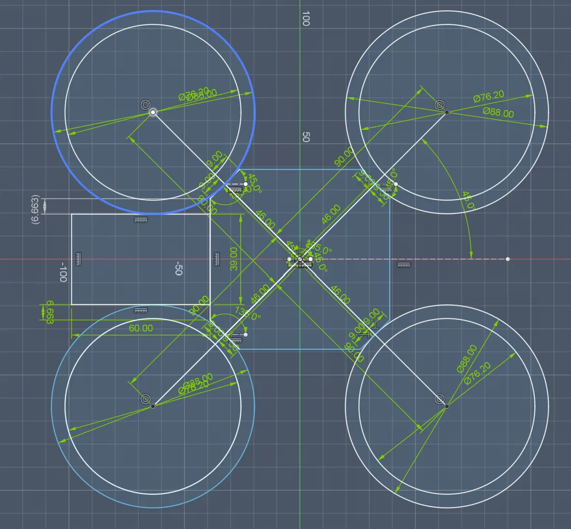
So I updated the box size to 39 mm and kept the length at 60 mm:
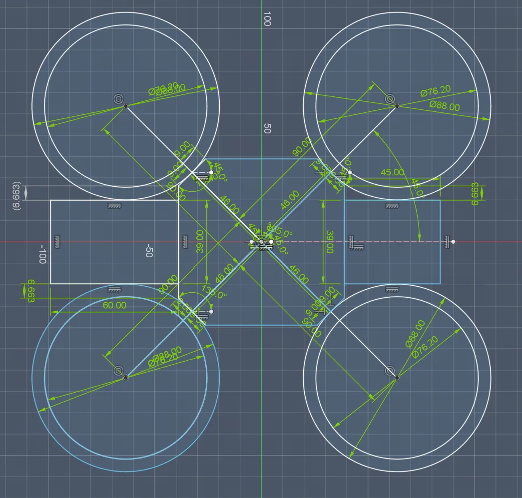
After that I started designing the bottom box for the battery. To help fine tuning the center of gravity later, I increased the length by 5mm (from 40mm to 45mm) so I can shift the battery if needed.
So the design looked like this:
Then I exited the sketch and wanted to extrude the base, but I wasn’t sure how thick it should be. Then I remembered I still need the mounting system for the motor arms, so I checked the screw sizes.
At first I couldn’t find any of that in my notes, so I had to google again and realized there are SOOO MANY different screw types. But after searching, I decided to use ultra thin low head M2×6 mm screws because they allow a thinner and cleaner design.
The screw head is about 0.8 mm thick, so I added 1 mm sothat the screw head can hid in that. Together with the 3 mm arm and base structure, everything fits: 3 + 3 + 1 − 1 = 6 => M2×6 mm screws
Next I cut the screw holes. I first marked the center lines, extruded 5 mm into the base, and created 2 mm holes. Because of 3D printing error, I increased them to 2.2 mm.
At first I thought the holes didn’t match the arm holes, but then I realized: one is for the heat insert, the other one is for the screw, so everything was actually fine...
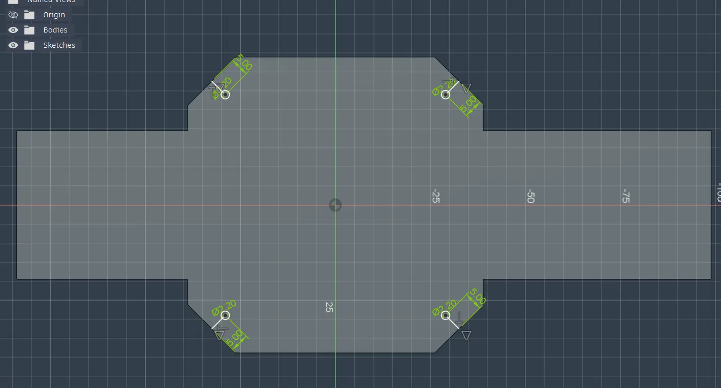
Lastly, I extruded the holes and added an extra hole so the screw heads can sit inside the base:
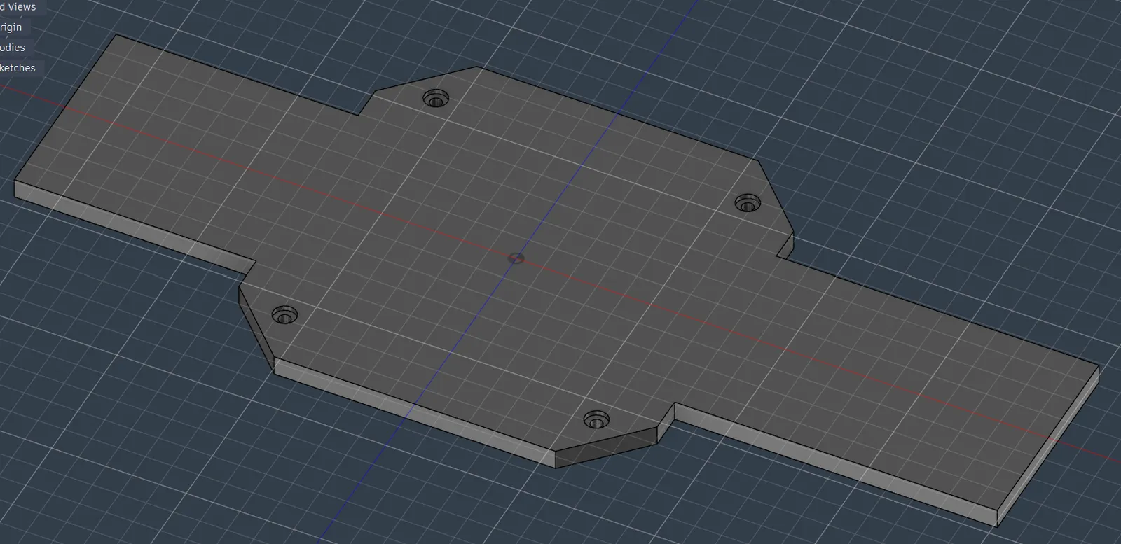
Happy with the progress today. I solved a lot of problems and started the base design. Next journal will be about the attachment mechanism for the arms and base.
Session recordings
Timelapse recordings of this session.